PWR Fuel

Basic Specification
| Type | 14×14 | 15×15 | 17×17 | |
|---|---|---|---|---|
| 10ft | 12ft | 12ft | 12ft | |
| Section size (mm) |
197 | 214 | 214 | |
| The number of spacers | 6 | 7 or 8 | 7 | 9 |
| Overall length of a fuel assembly (m) |
Approx. 3.5 |
Approx. 4.1 |
Approx. 4.1 |
Approx. 4.1 |
| Overall length of a fuel rod (m) |
Approx. 3.2 |
Approx. 3.9 |
Approx. 3.9 |
Approx. 3.9 |
| Fuel rod diameter (mm) |
10.7 | 10.7 | 9.5 | |
| The number of fuel rods (#) |
179 | 204 | 264 | |
| Pellet diameter (mm) |
9.3 | 9.3 | 8.2 | |
| The number of pellets (#) |
Approx. 240 |
Approx. 300 |
Approx. 300 |
Approx. 400 |
| Materials: |
|
|||
Manufacturing Process
Manufacturing Process in Tokai Plant(PWR Fuel)
01Reconversion Process(UF6 to UO2 powder)
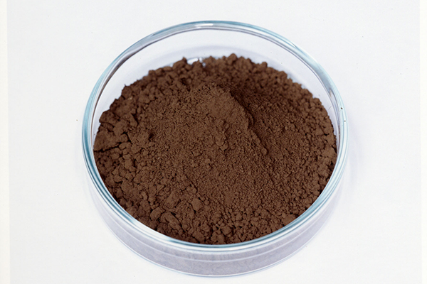
Low-enriched uranium hexafluoride, the starting material for the chemical conversion process, is vaporized. This gaseous uranium hexafluoride is then reacted with pure water to produce an aqueous solution of uranyl fluoride. Aqueous amonia is added to the uranyl fluoride, and the precipitate is filtered and dried to form a powdered form of ADU (ammonium diuranate). Further, through the processes of dewatering, drying, calcinations/reduction, and milling, the uranium dioxide powder is manufactured from the ADU.

02Pellet Fabrication Process (UO2 powder to UO2 pellet)
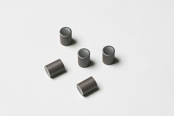
Granulated UO2 powder is pressed into pellet form by a rotary press. The "green" pellets are fired in a sintering furnace at a temperature higher than 1700℃ to produce UO2 pellets sinteral. The sintered pellets are then ground to specified dimensions.

03Fuel Rod Manufacturing (UO2 pellets to fuel Rod)
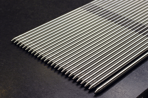
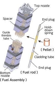
UO2 pellets are loaded into a zirconium alloy-cladding tube. Then, a pellet compression spring is inserted at one end, and end plugs are pressed into place at both ends. Top and bottom end plugs are welded to the cladding tube. The tube is filled with helium gas which is pressurized through a small vent hole in the top end plug. Finally the vent hole is seal-welded which completes the fuel rod assembly.

04Fuel Assembly Manufacturing (Fuel rod to fuel assembly)
Fuel rods are inserted into a matrix of six to nine grids (or spacers). Guide thimble tubes are mechanically joined to the grids (or spacers) and top and bottom nozzles are attached, completing the fuel assembly fabrication.

