


FUSION ENERGY : Experience and deliveries
SHARE


Distributors :
Experience of Fusion Reactor
MHI’s Plasma Vacuum Vessel
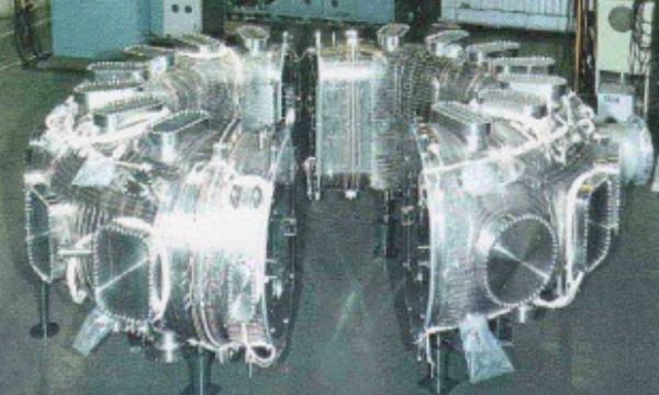
The plasma vacuum vessel system provides a high vacuum environment to confine generated plasma with functions to collect charged particles composed of ions and electrons. The vessel system is designed to bear huge mechanical loads which due to electromagnetic and thermal load.
|
Plasma vacuum vessel |
|
 |
Kyoto University, Heliotron DR
|
 |
JAERI(Note1), JFT-2M
|
 |
JAERI , JT-60U
|
 |
AIST(Note2), TPE-RX
|
- 1Japan Atomic Energy Research Institute
- 2National Institute of Advanced Industrial Science and Technology
Plasma Facing Component
Plasma facing components (PFCs) use heat and particle resistant materials to experience and resist high heat flux and particle flux exposed from plasmas, and to minimize radiation losses from the core plasmas. At JAERI experimental fusion reactor called JT-60U, The materials of PFCs had chosen high density graphite and carbon-fiber reinforced carbon composites (CFC) which have a high thermal conductivity and high melting point of material.
|
Plasma facing component |
|
 |
Nagoya University, ALT limiter of TEXTOR
|
 |
JAERI(Note), W-shaped divertor of JT-60U
|
- Japan Atomic Energy Research Institute
Experience of fuel systems
MHI’s Pellet Injector for JAERI(Note)
Pellet injector is a equipment used to supply fusion fuels into the core plasmas by fuel pellets consisted by solid hydrogen isotopes. A pellet injector designed and manufactured by MHI installed and injected ice pellets, with accelerated speed up to 2.3km/sec, into JT-60U to utilize high temperature and highly pressurized hydrogen gas as propellant gases.
|
Pellet injector for JAERI |
|
 |
JFT-2M Single pellet pneumatic injector
|
 |
JFT-2M 4-pellet pneumatic injector
|
 |
JT-60 4-pellet pneumatic injector
|
 |
JT-60 Centrifugal pellet injector
|
- Japan Atomic Energy Research Institute
MHI’s Tritium Handling System for JAERI(Note)
Fusion energy plants use two nuclides (hydrogen isotope) to fuse nucleuses as fusion fuels which are deuterium and tritium produced from lithium. Handling of tritium is a key technologies of the fusion system design.
In a fusion energy plant, tritium is gathered from a blanket system and the exhaust gas system. Then the tritium is purified, stored, and used as fuels for the plasmas, by creating an effective closed fuel cycle for the fusion energy systems.
MHI had supplied tritium handling systems with Palladium membrane diffuser and electrolysis cells to separate nuclide from mixed gases, and ZrCo bed bottles designed to absorb and store hydrogen gases.
Tritium handling system for JAERI
 TPL Air detritiation system (1985) |
 Fuel clean-up and Isotope separation system (1988) |
 Fuel clean-up system of TSTA in LANL (1990) |
- Japan Atomic Energy Research Institute
Components of fuel systems
 Pd membrane diffuser Operating Temperature: 300 to 450 deg. C |
 Ceramic Electrolytic cell |
 Active metal bed (ZrCo bed) |